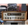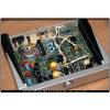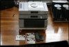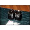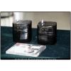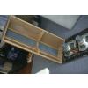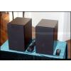
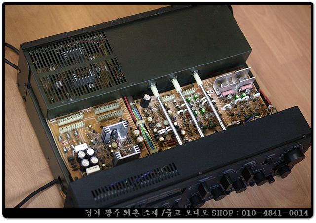


-내부 부품은 ALL FET 로 만들어진 희귀한 야마하 최상급 프리앰프 입니다.
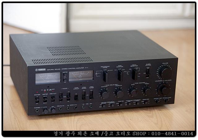
-상태 극상품 이며 다른기기와 절충교환 가능합니다.
-첼로 오디오 010-4841-0014
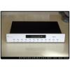
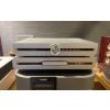
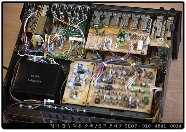
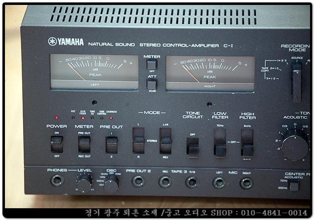
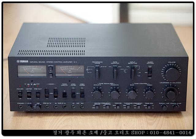
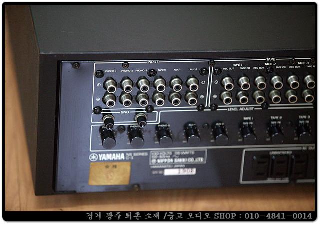
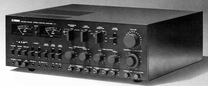
C-1은 모든 오디오 스테이지에 All-FET 회로를 사용한 분리형 스테레오 컨트롤 앰프입니다. 풍부한 입력단자의 선택은 3개의 포노입력과 각 입력에 대해 레벨 컨트롤을 제공하였습니다. 피크 레벨미터와 전체 오디오 시스템을 확인하기 위한 오실로스코프 같은 고급기능을 제공했으며, 특히 어쿠스틱 설정 (70Hz/300Hz )은 베이스 보강과 보컬 음악의 밸런스를 조정하기 위한 프레젠스(2kHz/4kHz) 파라메트릭 이퀄라이저를 제공하였습니다. 정밀 저항의 저음/고음 스위칭(턴오버 주파수 선택가능), 인간의 감성에 맞는 음장을 조정하는 연속 음량제어 및 완전한 톤 제어기능 등 음악성이라는 이 모델의 컨셉을 보여주기 위해 조화를 이루고 있습니다. 회로구성은 높은 신호대 잡음비를 제공했으며, FET 앰프는 필요에 따라 높은 증폭과 낮은 증폭을 다이내믹하게 선택하였습니다. 포노 이퀄라이저는 입력레벨의 넓은 범위를 허용할 수 있는 CR 타입 이퀄라이저로 전체적으로 부정적인 피드백을 제거하는 구성 및 +100V/-100V의 전원으로 동작하는 첫 번째 유닛 앰프 스테이지를 사이에 둔 직렬방식으로 2개의 유닛은 고급스럽고, 창조적인 구성으로 눈길을 끌었습니다. C-1은 진정한 드레드노트급 제품으로 B-1과 동시에 발매하려고 했지만, 이러한 설계요구로 발매가 1년간 지연되었습니다. 이 제품이 발매되었을 때, 전체 증폭방식을 사용한 B-1과 함께 사용할 수 있었으며, 오디오 세장에 FET를 사용한 최초의 제품이었습니다.
-이베이 국내 배송상품 가격은 6.043.244 원입니다.
https://www.ebay.com/itm/394631250819?hash=item5be1db0383:g:udcAAOSwxrpkZcaI&amdata=enc%3AAQAIAAAAwJp0O1t%2BHbKuiwBrYn3xQybaTL2CMfB1A%2F%2B61EinmLenhTU%2FiUnGVJalOiKVF3QMgl6J%2FefyiBCNruXko7Ztoynf%2FVJtlbYeV0IwbUDAfJSfIxBGJMImhaI%2FKZKZqIWVFQaUH3PujEybhfAKag6EmSFmAviR3lMtQ%2BaW1Iap%2BtwUZ8OaFkqK%2Fq9igQsALvloY%2BUqxQWqJZ2FBhiZoxMFT0PjFt3NjBtBggzB%2Frvwgg8IOejjbUi3IapTer0EUAF8pA%3D%3D%7Ctkp%3ABk9SR86XkqOaYg
-
YAMAHA C-1(C-I)
-
* Made-to-order products
¥ 400,000 (around 1975)
Commentary
This control amplifier was developed to maximize the performance of the stereo power amplifier B-I.
Development of C-I was started at the same time as B-I, but it took much more time to complete because of its extremely complex structure.
By combining C-I and B-I, it is possible to make the signal path into a complete FET.
The C-I circuit consists of a combination of two types of unit amplifiers whose signal paths are all-stage FETs.
For circuits that require relatively high amplification, such as equalizers and tone controls, we use a unit amplifier A, a 3-stage direct-coupled circuit consisting of N-channel differential amplification at the first stage, P-channel grounded phase inversion amplification at the second stage, and N-channel SRPP at the last stage. For the first stage amplifier circuit, we select an FET with low noise and high Gm. In addition, we select two FETs with the same electrical and temperature characteristics and use them as a pair. The differential circuit also realizes extremely low-noise characteristics because common-mode noise components such as external noise and noise from the power supply do not appear in the output. Furthermore, the output stage is SRPP, which is combined with high power supply voltage to obtain sufficient amplitude linearly.
For circuits that do not require much amplification, such as Aux, Tuner, Tape, and Pre out, a unit amplifier B is used as a buffer amplifier, which uses a 3-stage direct circuit consisting of first stage differential amplification, second stage P-channel source grounding, and last stage N-channel source follower.
Unit Amplifier A and Unit Amplifier B were first conceived by FET and are circuits designed for FET. They are designed not only to replace transistors with FET but also to demonstrate the performance of FET devices.
The equalizer circuit is a CR type using two unit amplifiers A for one channel.
The output of the cartridge is amplified by the first stage unit amplifier, passed through the RIAA compensation circuit consisting of a capacitor and a resistor, and amplified by the second stage unit amplifier. The first stage unit amplifier is supplied with a high power supply voltage of + 100 V and -110V at a constant voltage in order to increase the allowable input and SN ratio. The output of 60 Vr. m. s or more is obtained with low distortion. The allowable input is sufficiently high by using the level control.
Since a CR type equalizer is used, there is almost no degradation of the distortion factor caused by the equalizer circuit, and the problem of the time constant of the feedback circuit is solved.
The C-I has a tone circuit switch so that it can be used as a simple preamplifier with just one switch.
The tone circuit switch separates the tone control, tone equalizer, filter, and loudness circuit from the signal path. The equalizer output flows through a flat amplifier to the main amplifier.
In order to improve various characteristics of the C-I, we thoroughly examined the bare characteristics of the unit amplifier itself, and obtained excellent frequency characteristics, phase characteristics, transient characteristics, and low distortion rate characteristics by applying stable negative feedback after finishing it as wide band and low distortion rate as possible. In addition, various characteristics change depending on the routing of wiring and the print pattern, so we have given sufficient consideration to these characteristics.
The S / N ratio has been improved by lowering the impedance of the whole circuit, examining shielding, wiring and component arrangement, and using low-noise parts. In addition, in order to improve the S / N ratio in actual use, a high-precision special 4-connected volume of 2 circuits per channel is used. This 2-connected volume is put into the input and output sides of a tone circuit amplifier (flat amplifier with gain 14.3 dB when tone circuit is off). The -∞~- is adjusted at the output side of the amplifier up to 20 dB, at the input side of the amplifier up to -20 to -5.7 dB, and at the output side of the amplifier up to -5.7 to -0dB. As a result, the S / N ratio is improved by 6 to 14 dB in the normal operating range and by 14 dB when the volume is fully reduced.
The equalizer element for determining the RIAA deviation of the equalizer circuit consists of a metal film resistor with a small temperature characteristic of ± 1% error, a Styrofoam capacitor and a Mylar capacitor with a different rate of change in capacitance with temperature, and a block capacitor with a capacitance error within ± 1% over a wide range of -10 ℃ to + 80 ℃. This makes the RIAA deviation accurate to ± 0.2 dB.
For tone control, both Bass and Treble use an attenuator that combines a 21 position rotary switch with a high-precision printing resistor to reduce step error and interlocking error.
In addition, the turnover frequency can be and precise control is possible.
With a tone equalizer, you can control the Acoustic tone of the listening room and the Presence tone of the program source. You can switch the center frequency of each control.
The control is an 11-point step type using high-performance L and C.
Equipped with low filter and high filter.
Each filter can switch the cut-off frequency in two stages. The cut-off frequency is -3dB, and after that, attenuation is performed with a sharp and accurate slope.
It is equipped with a continuous loudness circuit that can adjust the audibility according to the volume and sound field of the listener.
The loudness curve ranges from 0 to -20dB and provides an accurate correction curve to match the equiloudness curve.
Equipped with a high-precision peak level meter.
The meter circuit consists of a logarithmic compression circuit and a linear detection circuit in one negative feedback loop to reduce the indication error due to variations in the elements of the detection circuit. In addition, the indication error at each level is reduced by sharing between two logarithmic amplifiers -30dB or less and -30dB or more.
The level of the Pre out and Rec out signals can also be monitored by the meter selector switch, and the -30dB meter attenuator supports a dynamic range of -50dB to + 35 dB.
It can be used as an independent peak level meter by means of a switch on the rear panel. You can monitor the level of the sy passing power of the main amplifier and the output of other amplifiers.
It contains a pink noise oscillator with constant energy per octave band and a sine wave oscillator of 70 hz, 333 hz, 1 khz and 10 khz.
Since the output of this oscillator can be taken out independently, it can be combined with a peak level meter to check C-I and test and measure audio equipment.
The tape circuit is installed in the Route 3, and simultaneous recording by 3 units and mutual tape copying of each deck are possible.
Since the tape monitor switch and recording mode switch are independent, tape copying is possible regardless of source play. When recording is not performed, the recording mode switch can be set to Rec out off. By disconnecting the Rec out terminal from the signal path, the load effect on the signal path due to the decrease in input impedance of the deck with the shield line capacity and power supply turned off can be eliminated.
The headphone amplifier uses a pure complimentary service OTL circuit.
The input impedance of the Phono terminal can be switched to six levels, and the input sensitivity can be adjusted by the input level control that changes the negative feedback of the pre-stage unit amplifier of the equalizer circuit.
The microphone amplifier uses the unit amplifier at the first stage of the equalizer circuit.
Equipped with an audio muting switch, the gain of the amplifier can be reduced by -20dB.
In the off position, the signal to the Pre-out jack is cut off, but all other circuits operate, so it can be used for listening with headphones only.
LED is used for the monitor indicator.
Equipped with a remote control terminal exclusively for B-I.
.jpg)
.jpg)
.jpg)
.jpg)
.jpg)
Model Rating
| Type | Control amplifier | ||||||
| Amplifier Characteristics | |||||||
| Input Sensitivity / Impedance | Phono1, 2 : 2 to 8 mV (variable) / 30k Ω, 41k Ω, 47k Ω, 53k Ω, 59k Ω, 100k Ω Phono3 : 2 to 8 mV (variable) / 47k Ω Aux1, 2, Tape PB1, 2, 3 : 150 mV or more (variable) / 50k Ω Mic : 2mV/50k Ω Ext Meter : 775mV/0dB/110k Ω |
||||||
| Maximum allowable input | Phono : 25 mV to 100 mV (20 Hz) 200 mv ~ 800 mv (1 khz) 800 mv ~ 3200 mv (10 khz) Aux1, 2, Tape PB1, 2, 3 : 12 v (at sensitivity of 150 mv) Mic:200mV |
||||||
| Output Level / Impedance | Pre out1, 2 : 775mV/300 Ω Rec out1, 2, 3 : 150mV/1k Ω Headphone : 50 mw (8 Ω) / 47 Ω OSC : 775mV/180 Ω |
||||||
| Maximum output level | Pre out1, 2 : 7.75 V Rec out1, 2, 3 : 12 V |
||||||
| Frequency characteristic | Phono1, 2, 3 : 30 Hz to 15 kHz ± 0.2 dB (RIAA deviation) Aux1, 2, Tuner, Tape1, 2, 3 : 5 Hz to 100 kHz + 0 -1.5 dB Mic : 20 Hz to 20 kHz ± 0.5 dB |
||||||
| Signal-to-noise ratio (IHF-A network) | Phono1, 2, 3 : 70 dB (IHF-A network) Tuner, Aux1, 2, Tape1, 2, 3 : 90 dB (IHF-A network) Mic : 60 dB (IHF-A network) |
||||||
| Noise level | Headphone : 0.019 μ W (8 Ω) Residual noise : 7.75 μ V (Volume min) 15.5 μ V (Volume-30dB) |
||||||
| Distortion Factor (20 Hz to 20 kHz) | Phono1, 2, 3 : 0.02% or less (775 mV) 0.02% or Less (5 v) Tuner, Aux1, 2, 3, Tape1, 2, 3 : 0.02% or less (775 mV) 0.02% or Less (5 v) Mic : 0.02% or less (775 mV) |
||||||
| Tone control characteristics |
|
||||||
| Tone equalizer characteristics | Acoustic(fc= 70 Hz, 300 Hz) : 0, ± 0.5, ± 1, ± 2.0, ± 4.0, ± 6.0 dB Presence (fc= 2 kHz, 4 kHz) : 0, ± 0.5, ± 1, ± 2.0, ± 4.0, ± 6.0 dB * Completely flat at position 0 |
||||||
| Filter characteristic |
|
||||||
| Continuously variable volume accuracy |
|
||||||
| Audio Muting | -20dB off (meter, Headset working) | ||||||
| Oscillator Characteristics | |||||||
| Frequency | 70 Hz, 333 Hz, 1 kHz, 10 kHz, Pink Noise Switching | ||||||
| Output level | Rec out:150mV Pre out:775mV Ext out : 0 ~ 775 mV Variable |
||||||
| Level Meter Characteristics | |||||||
| Indication range | -50dB to + 5 dB | ||||||
| Indication error | -20dB to + 5 dB ± 1 dB -20dB to -40dB ± 2 dB -40dB to -50dB ± 3 dB |
||||||
| Frequency characteristic | 20 Hz to 20 kHz ± 1 dB | ||||||
| Response time | 100 μ sec | ||||||
| Recovery time | 1sec | ||||||
| ATT | -30dB | ||||||
| Ext Meter in sensitivity / impedance | 775 mv (0 db) / 110k Ω | ||||||
| <General> | |||||||
| Semiconductor used | FET : 110 units Transistor : 143 units IC : 4 Diode : 58 pcs Zener diode : 2 pcs LED : 6 pcs |
||||||
| AC outlet | Switched : Route 3, 200W Unswitched- Route 3, 400W |
||||||
| Power consumption | 55W | ||||||
| External dimensions | Width 460x Height 170x Depth 389 mm | ||||||
| Weight | 17kg | ||||||
.jpg)