논란이되고 있는 캐소드 바이패스 콘덴서에 대한 교과서적인 내용입니다. 좀 길긴 하지만 정확한 이론을 설명하고 있어 덧붙여 봅니다. 한번쯤 읽어보실만 합니다.
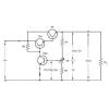
간단히 요약하면 캐소드 바이패스 콘덴서의 역할은 그리드 시그널 신호에 의한 바이어스 전압을 안정시키기 위해서 AC 신호를 옆으로 돌려 통과시키기 (BYPASSING) 입니다. 내용이 좀 길어 주파수에 대한 바이패스 콘덴서의 역할 변화와 적정 바이패스 콘덴서 용량 계산 방법은 생략했습니다. 하지만 진공관 기초 이론 서적에는 대부분 나와 있을 것입니다. 참고가 되시길 바랍니다. 덧붙인 그림은 위쪽이 1-22, 아래쪽이 1-23입니다.
Cathode Bias
In circuits using cathode bias, the cathode is made to go positive relative to the grid. The effect of this is the same as making the grid negative relative to the cathode. Because the biasing resistor is in the cathode leg of the circuit, the method is called CATHODE BIASING or CATHODE BIAS. A triode circuit using cathode bias is shown in figure 1-22.
The only difference between the illustrated circuit and the one used to demonstrate triode operation is the elimination of the battery, Ecc, and the addition of circuit components Rk, the cathode-biasing resistor; Ck, the cathode ac-bypass capacitor; and a grid resistor (whose purpose will be explained later). When the tube conducts, current flows from the battery through Rk to the cathode, through the tube to the plate, and through RL to the positive terminal of the battery. The current flowing through Rk will cause a voltage drop across Rk. The bottom of Rk goes negative while the top goes positive. This positive voltage at the top of Rk makes the cathode positive relative to the grid. You may wonder what purpose Ck serves in this circuit. Ck serves as an AC BYPASS. Without Ck, the bias voltage will vary with ac input signals. This is particularly troublesome in the higher frequencies like those found in radio receivers. Rk, the cathode-biasing resistor, is used to develop the biasing voltage on the cathode. The input signal will be developed across Rg. You will read more about the circuit component later in this chapter. Cathode-biasing voltage is developed in the following manner. As we mentioned earlier, the bias voltage will vary with the input unless Ck, the cathode bypass capacitor, is used. To understand how the bias voltage will vary with an ac input signal, disregard Ck for the moment and refer to figure 1-22 again. Notice that under quiescent conditions, the voltage drop at the top of Rk is +10 volts. Now let’s apply the positive-going signal illustrated to the left of the tube. When the positive signal is applied, conduction through the tube will increase. The only trouble is that current through Rk will also increase. This will increase the voltage drop across Rk, and the cathode voltage will now be greater than +10 volts. Remember, at this time the plate is going negative due to increased conduction through the tube. The combination of the negative-going plate and the positive-going cathode will decrease the electrostatic attraction across the tube and lower the conduction of the tube. This will reduce the gain of the tube. When the negative-going signal is applied, conduction through the tube decreases. Current through Rk decreases and the voltage drop across Rk decreases. This causes the cathode to go more negative, which tends to increase conduction through the tube. A negative-going signal is amplified by decreasing plate current and allowing the plate to go positive (remember the 180º inversion.) Thus, increasingshown in figure 1-22.
on the negative half-cycle decreases the gain of that half-cycle. The overall effect of allowing cathode biasing to follow the input signal is to decrease the gain of the circuit with ac inputs. This problem can be overcome by installing Ck. The purpose of Ck is to maintain the cathode bias voltage at a constant level. In common usage, the action of Ck is referred to as "bypassing the ac signal to ground." The action of Ck will be explained using figure 1-23. View A shows the circuit under quiescent conditions. With some conduction through the tube, the cathode and the tops of R k and Ck are at +10 volts. In view B, the positive-going signal is applied to the grid. This causes increased conduction through the tube, which attempts to drive the cathode to +20 volts. But notice that the top of Ck is still at +10 volts (remember capacitors oppose a change in voltage). The top plate of Ck is, in effect, 10 volts negative in relation to the top of Rk. The only way that Ck can follow the signal on the top of Rk (+20 volts) is to charge through the tube back to the source, from the source to the lower plate of Ck. When Ck charges through the tube, it acts as the source of current for the cathode. This causes the cathode to remain at +10 volts while the capacitor is charging. View C of the figure shows the same signal. Under these conditions, conduction through Rk will decrease. This will cause a decrease in current flow through Rk. Decreased current means decreased voltage drop. The top of Rk will try to go to +5 volts. Ck must now go more negative to follow the top of Rk. To do this, current must flow from Ck through Rk, to the top plate of Ck. This discharging of Ck will increase current flow through Rk and increase the voltage drop across Rk, forcing the top to go more positive. Remember, the voltage drop is due to current flow through the resistor. (The resistor could care less if the current is caused by conduction or capacitor action.) Thus, the cathode stays at +10 volts throughout the capacitor-charge cycle. There is one point that we should make. Ck and Rk are in parallel. You learned from previous study that voltage in a parallel circuit is constant. Thus, it would seem impossible to have the top of Rk at one voltage while the top plate of Ck is at another. Remember, in electronics nothing happens instantaneously. There is always some time lag that may be measured in millionths or billionths of seconds. The action of Ck and Rk that was just described takes place within this time lag. To clarify the explanation, the voltages used at the components Rk and Ck were exaggerated. Long before a 10-volt differential could exist between the tops of Rk and Ck, Ck will act to eliminate this voltage differential.
The capacitor, then, can be said to regulate the current flow through the bias resistor. This action is considered as BYPASSING or eliminating the effect of the ac input signal in the cathode. For all practical purposes, you can assume that ac flows through the capacitor to ground. But, remember, ac only appears to flow across a capacitor. In reality the ac signal is shunted around the capacitor.